Thursday 30 November 2017

Current progress, in a few points

Since the start of this school period on November 13th, we continued working on creating our prototype. Because it is our penultimate school period, a large part of our timetable is filled with "Project" time.

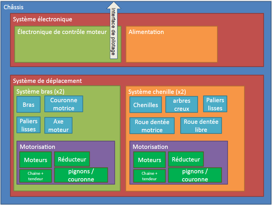
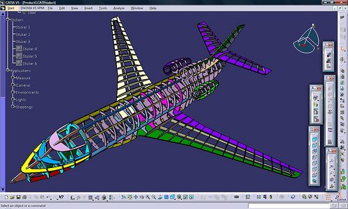
To begin with, we had received our motors and planetary gearboxes, received gearwheels that we had bored to the right dimensions, we had begun programming the Arduino Mega,  finished our 3D design and were controlling the parts' blueprints.

As of now, we have machined a large majority of our metal parts and begun assembling the prototype's frame. Some parts had to be modified to take into account the characteristics of our school's workshop. For exemple one major part, the wheels, have to be sintered since they cannot be milled. Also, the original RICA III motors were joined to the frame through a sinter support.


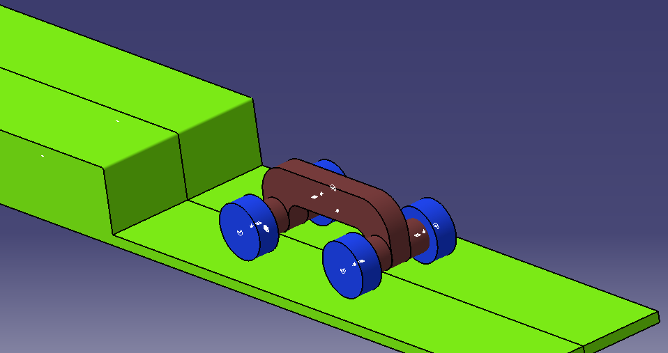
For testing and validation purposes, we also worked with the other MKX team to produce a step to the right dimensions (30*28 cm).

Concerning the electronics and programming part of our project, we : 
 - realized the main program of our Arduino Mega, 
 - received the encoders and began integrating them,
 - created the encasing for the electronics.

At this point, we can control our motors with a Xbox 360 controller. Still, we are missing some components and cannot finish programming at the moment.

We also worked on a 3D simulation of our prototype's movements on the software Unity (More details in this post).

We are halfway through this period, and "Project" time will be less present in our timetables, but we plan to continue working and if possible have a fully assembled prototype for December 15th.

Simulation - Work in progress

We keep working on the simulation and as you can see below these lines, we updated the environnement of the simulation. We also improved the physics and we enhanced the camera vision.

Some details will be implemented but the next major step is to fit the simulation to the real behavior of our prototype.


(Use full-screen mode)


Tuesday 28 November 2017

Into the simulation

As a bonus, we are developping a full-scall simulation of our robot. We firstly used this simulation to test our control program. Now we want to improve it and we aim to use it for piloting assistance.
 
The simulation uses datas sent by the robot from the closed loop controle. Our goal is to make the simulation as real as possible in term of kinematics, kinetics and dynamics to make it usable.

                                                                           Scripting C# on visual studio                                       Screenshot of the modelling

The simulation is developped with unity 3D wich combines graphical programming and scripting.
Here is a demonstration of our work wich is not over. We will have to match the simulation with the real behavior of the robot and add textures.

                                                                                               Working on the simulation


Manufacturing the RICA IV

As part of the realization of the RICA IV, we manufactured most of the parts on the school's mechatronics platform. We did the machining by ourselves, assisted by our teachers when it was needed. Many pieces were made on conventional lathes. The most complex parts were made on CNC machines (5-axis lathe and milling machine) that we programmed. For the flat parts (frame and arms), we used a CAM program that we did on CATIA V5.  

 
                                                    Conventional lathe                          numerically controlled milling machine                                band-saw

Electric housing


The electric housing is now manufactured. It is composed of 4 pieces mounted together around the motors support.
The two parts, where the electronics will be integrated, were printed with wire while the top plate was printed in two parts by sintering.


                                       Motors support (sintered)                 Electronics support (3D printed)                      Top plate (sintered)


So that the whole mounts correctly on the frame, we had to slightly sand. Now we will start the integration of the electronics !

Our cursus' Skill Repository

Note : As a reminder, you could check out the Mechatronics Wikipedia page linked here to get a deeper understanding of how our cursus is designed.

Our school uses a skill repository to check and improve the growth of us apprentices. It is mainly devided into three categories : Project management, Product management and Organization.

All our tools are in this box

If you look deeper in those categories, you will see more precise skills that represents all that a mechatronics engineer must learn and use in his career.
Those skills mix together, forming the base of Mechatronics Engeneering

If you are interested in the meaning of those skills, please check this link to see a full display of those skills' descriptions and a table of all our posts organized as such.

Monday 12 June 2017

Designing the Rica IV prototype


We are currently in the Rica IV prototype design phase. The goal is to build a functional robot which can climb stairs in normal conditions. For the prototype we don't take into account nuclear requirements. We only work on the crossing system.

We previously made a state of the art "climbing robot " to see what solutions already exist to answer our customer needs. We finally chose a 4 arm robot with tracks like the "chaos robot" architecture :
Résultat de recherche d'images pour "robot chaos"


Regarding our budget, we decided to mechanically synchronise arms, two per two and tracks as well. It allows us to reduce the number of motors from 8 to 4.
Thanks to this cost-reduction, we can make a full scale robot meeting all displacements and crossing requirements.

To design the robot, we based our study on some tools like PBD (Physical Block Diagram) to define in detail each sub-assembly. Then we achieved the CAD and we chose all COTS (components off-the-shelf).

Here is the final architecture of our prototype (sheets components doesn't appears in detail)  :


After several iterations within the team, we validated this architecture. Then we can start CAD and calculate all internal needs (like torque provided by motors, shaft's diameters...).


A prototype in the making

As you dear visitors know, for the past two years we have worked towards developing a new robot called the RICA IV succeeding the RICA III designed by Cyberia.


Three weeks ago, we were asked to create a functional prototype for the system. As we could never create a complete RICA IV by our deadline, we are only working on creating a robot capable of climbing over stairs.


Our deadline is the 19th of June, next monday. On this day, we are supposed to deliver documents and blueprints to create the system, so that the technical team at the school can prepare the next period. During that period we will create the system with the technical team's help and finish with a test of our prototype.


Professors and technicians are currently lending us a hand in designing the prototype and giving advice to prevent trouble during the development process.


As of today we developed the body and selected our electrical motors. We shall communicate on those matters in the next few days.


We thank you for following us on this new project, and hope you like our posts.

Sunday 12 February 2017

Linux robot

During our engineering training, sometimes our teachers give us the task of working in interesting projects, our last work was to program a robot so we could control it with a smartphone. This project was so interesting that we just couldn’t talk about it in this blog.

The robot is already build, it’s a mobile robot that has four wheels, a clamp and many sensors (Infra-red, ultrasounds, gps, compass…). 
Our mission was to program the robot so he can be controlled by an application on a smartphone. The robot has to send all the sensors data and the image of its camera to the smartphone and the pilot can use the phone like a remote to move the bot thanks to wifi. The communication architecture used here is called client-server, it means that the server is passive and waiting for request that the client send. In our case the server is the robot and the client is the smartphone.

The robot is controlled by a raspberry-pi, it’s a nano-computer that has the size of a credit card and that work with the operating system linux. It’s used a lot in engineering to do prototypes in embedded electronics because it’s cheap and easy to use. We did realise our software in using the java language. The smartphone app was realized by another group in html and JavaScript.


At the end we did a contest off glass catching with our bots, it was a big accomplishment for us.

Pushing robots, software and strategies

In a previous article, we wrote about the hardware of our pushing robots (http://rica4-by-mkx.blogspot.fr/search/label/Pushing%20robots), we will now present the software part.


To develop this software we used the Arduino IDE with a library that allows us to control the motors easily.

Our program was made of two big parts, the first one to move forward in front of the RICA, and the other one to follow another robot on the side. To choose the part of the program that we want to use, we put a switch on the robot.


To move forward in front of the RICA, we use a simple strategy: every motor was control by the infrared sensor located on the same side. If the distance is too high on a sensor, the track of this side goes forward, if the distance is too low, the motor goes backward. Moreover, the speed of the motor is proportional to the gap between the desired distance and the actual distance.

To follow by the side, we use two infrared sensors. If the rear sensor doesn’t sense the other robot, the robot moves forward, if it’s the front sensor, the robot moves backward. Another part of the program was made to keep the robot at a constant distance from the other robot and allowed it to turn following the other robot.


Finally, last week, we improved this first program by adding it a dashboard, to do this we used the software labview. With this interface we can adapt parameters of every robot in real time.


The next step is now to make our pushing robots communicate between them.

Thursday 9 February 2017

The Creativity Seminar

On the 2nd and 3rd of February, the EMA (Ecole des Mines d’Alès) hosted its annual Creativity Seminar, a meeting for students of various schools to be taught methods and techniques to innovate, using the imagination of a group rather than a single person.

16463136_1619431398073601_8489585818251489057_o.jpg

This event’s main organizer is Michel Ferlut, the Economic Development Director of our school, who did all kinds of meetings and courses on creativity and innovation over the years.

Michel-Ferlut.jpg

After a presentation on the topic of innovation to warm us up, representatives from numerous companies such as Total, Cora or SNCF would take a group of approximately ten students and teach them over 10 hours their own methods and their experiences.

16423022_1619432414740166_2780646708558225105_o.jpg16300366_1619431941406880_2113087926771369259_o.jpg
The meeting ended on a bright note, students participated in a Flash Mob on the song “Different kind of prostitute” by Chilly Gonzales, Mr. Ferlut cheerfully gave us one joke after another and we could hear the schools sing their “hymns”.

But the end of the meeting isn’t the end of our creative work. Companies would now put students’ imagination to the test with the Creativity Challenge. Each company gave a theme and objective to work on. Students of the EMA have now 5 weeks to offer a solution to their problems. The students with the most successful ideas would receive various rewards from the companies such as mediatisation or privileged partnerships.

As apprentices, we have a different challenge to take on. On the subject of the RICA, we have one week to come with innovative ideas and present them in the form of a Pecha-Kucha (automatically transiting diapositives, 20 pictures x 20 seconds each).

pk1.png

Each group used the techniques they learned during the seminar to find solutions with no limitation by reality. The Pecha-Kucha will be presented the Friday 10th of February before the school’s teachers.

We hope some of our ideas will be the start of bigger innovations in the future.

20140723_152638_179693799-wavebreakmedia-ltd.jpg

NB : A fun fact is that “Seminar” comes directly from the Latin word “Seminarium” which translates in English to “plant nursery”, a fitting metaphor on the theme of creativity if you imagine an idea is like a plant.

rosier pep2.jpg

Wednesday 8 February 2017

CATIA and Crossing function modelization


We began working on the mobility system of the RICA robot : movements, crossing over obstacles…


So far we had two different classes : the first one’s objective is creating a complete plan of the robot architecture using Core, the second’s is modelizing the robot crossing over a 30 cm tall step on CATIA v5. I will elaborate on CATIA further below.

CATIA is one of the more complete CAD tools on the market and is used by important companies such as airplane companies to conceive their planes and realize calculations.

DS-CATIA-Logo-300x243.png3467813675_3da53e1c45.jpg


For the class we practiced creating simple forms such as wheels and tried to make them cross the step by applying different factors : speed, torque, lack of gravity… All of this is possible through the SimDesigner add-on. By creating a model, we can then study the effects of those different factors on the movement. Proceeding step by step we then modelized two wheels, then four.

Sans titre.png

We are now one step closer to create the mobility system we are expected to do.

Tuesday 24 January 2017

Nuclear radiations


C:\Users\Paulo\AppData\Local\Microsoft\Windows\INetCache\Content.Word\danger-radiation-sign.jpg


When we hear documentaries or conversations about the nuclear field, you will always hear about radiations. But what are those harmful rays ? In this article we will answer to this questions and we will describe the different measures used in this field. Finally we will explain why nuclear radiations can be harmful for robots.
Radiations are particles and energy emissions. we are constantly surrounded by many kinds of radiations like radio waves or sunlight. A lot of those are not harmful to humans or to electronics devices. In big quantity some of them can warm water (Microwaves…) or create parasite in electronics.
Ionizing radiations are some kind of ray that can split molecules or atoms into ions. Those ions could emit ionizing radiations too. Ionizing rays can be dangerous for the human body depending on the amount received. They can create tumours or necrosis.
In nuclear environment some substances are emitting ionizing radiations, they are named radioisotopes (Uranium, tritium...), and they can emit four kinds of rays:
  • Gammas radiations (Photons emission),
  • Alphas radiations (Helium nucleus emission),
  • Beta radiations (electron or positron emission),
  • Neutron radiations (Neutron emission, these ones are not ionizing rays). C:\Users\Paulo\AppData\Local\Microsoft\Windows\INetCache\Content.Word\322504-14782862845fbc1a65b8337ede57f7ee.jpg
The dose of radiation is the quantity of energy transmitted by them to the organ or the tissue touched, three doses concepts exists expressed with different units:
  • The absorbed dose represent the energy transmitted by the radiation without taking account of the kind of radiation expressed in Gray (Gy),
  • The equivalent dose take account of the type of radiation (alpha, beta…) and is expressed in Sievert (Sv),
  • The effective dose take account in addition of the kind, the organ that suffer of the beam they are expressed in Sievert too.
Now let’s return to our favourite robot. All the radiations described above can be found in high doses in the blind cell (that’s why humans can’t go here by the way) and unfortunately the RICA can be harmed by those rays too. More precisely its electronics parts are sensitives to the radiations.
One of the major problematic in the realization of electronics systems that has to work in nuclear environment is to make them resistant to ionizing radiations.
A lot of little electronics components are made of one kind of materials called semiconductors (the processor of your computer for example). This components can be destroyed by neutrons or gammas radiations.
In addition the risk exist that the robot could carry contaminated particles (that emit radiations), the RICA has to get out of the cell at the end of its intervention so it has to be contaminated as little as possible. So that’s why we need to protect the electronic part of the RICA so it will stay functional in the cell and make sure that the robot doesn’t bring contaminated particles (or as little as possible).  
Now you know what the so called nuclear radiations are and why they can be bad for the RICA.
We hope that you liked this article.

In a future article we will explain how the robot will be protected against radiations and how answer to the need expressed upper.

Tuesday 17 January 2017

RICA'S evolutions

The CEA express the need to investigate blind cells with a high level of radiation so where human can’t survive. The RICA project is born. It is named RICA for “Robot d’Inspection de Cellule Aveugle” which means blind cells inspection robot. This robot will be modified to cover new needs indeed by the investigation of new cells and different modules to carry. In this article we will review the three previous RICA version which conduct to our project the RICA IV.


RICA I

To create the RICA I the CEA work with CYBERIA to modify “HUGGY” robot and adapt it to the nuclear environment. It also have to be modified to manage the camera and to add a radiation level censor.
The RICA I is divided in two sub-systems: the motorisation and the camera bloc.


A wheel have been added under the camera to ensure a good mobility on flat ground and allow the pilot to take picture of all the blind cells.
This robot have been used in April 2007 in order to examine a cell and especially tanks which contain radioactive products. The RICA I is narrow because for this inspection it was introduce in the cell through a coring.


After this inspection the CEA express new needs. It appears that the wheel under the camera bloc is not enough efficient and the robot have to be more mobile with better crossing capabilities. It was also very difficult to decontaminate the wheels and the coaxial cable. So new technical solutions have to be found.


RICA II

The RICA II is the improved version of the RICA I and take into account feedbacks from previous inspections.
The RICA II is still composed of two sub-systems: the camera bloc and the motorisation. But now the difference is that these two parts are assembled to form a tank.


At the end of 2007 several tests have been done and the RICA II satisfied the new requirements of the CEA.


RICA III

The RICA III is also an evolution of the RICA I and II. You can find a precise description of this robot on our blog, please follow this LINK.

This robot was made because the CEA need to inspect other blind cells with difficult access and because they want to carry more precise camera or a robotic arm.  So the crossing and the transportation capabilities of the RICA II was sufficient.


RICA IV

The RICA III is aging and in operation for more than eight years now so the needs of the CEA have changed and the RICA III performances are not sufficient.
That’s why the CEA request them to improve RICA robot and create the version IV. The first goal is to improve crossing capabilities. The RICA IV have to cross obstacles in step configuration with the following dimensions:


This robot also have to go under an obstacle which is 30 cm from the ground, it have to transport heavy sub-systems (gamma camera, robotic arm, …), these sub-systems need to be easily changed, it can’t weigh more than 100 kg, have to resist from important radiation, the command system have to be improved to be more ergonomic, etc. This robot will be used in a very aggressive place with a lots of constraints which lead to a complex design.


So our work will be difficult for this project and we need robust methods to design this new robot like system engineering and all the expertise of our school.