Tuesday 24 January 2017

Nuclear radiations


C:\Users\Paulo\AppData\Local\Microsoft\Windows\INetCache\Content.Word\danger-radiation-sign.jpg


When we hear documentaries or conversations about the nuclear field, you will always hear about radiations. But what are those harmful rays ? In this article we will answer to this questions and we will describe the different measures used in this field. Finally we will explain why nuclear radiations can be harmful for robots.
Radiations are particles and energy emissions. we are constantly surrounded by many kinds of radiations like radio waves or sunlight. A lot of those are not harmful to humans or to electronics devices. In big quantity some of them can warm water (Microwaves…) or create parasite in electronics.
Ionizing radiations are some kind of ray that can split molecules or atoms into ions. Those ions could emit ionizing radiations too. Ionizing rays can be dangerous for the human body depending on the amount received. They can create tumours or necrosis.
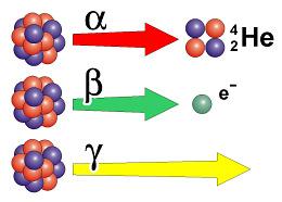
In nuclear environment some substances are emitting ionizing radiations, they are named radioisotopes (Uranium, tritium...), and they can emit four kinds of rays:
  • Gammas radiations (Photons emission),
  • Alphas radiations (Helium nucleus emission),
  • Beta radiations (electron or positron emission),
  • Neutron radiations (Neutron emission, these ones are not ionizing rays). C:\Users\Paulo\AppData\Local\Microsoft\Windows\INetCache\Content.Word\322504-14782862845fbc1a65b8337ede57f7ee.jpg
The dose of radiation is the quantity of energy transmitted by them to the organ or the tissue touched, three doses concepts exists expressed with different units:
  • The absorbed dose represent the energy transmitted by the radiation without taking account of the kind of radiation expressed in Gray (Gy),
  • The equivalent dose take account of the type of radiation (alpha, beta…) and is expressed in Sievert (Sv),
  • The effective dose take account in addition of the kind, the organ that suffer of the beam they are expressed in Sievert too.
Now let’s return to our favourite robot. All the radiations described above can be found in high doses in the blind cell (that’s why humans can’t go here by the way) and unfortunately the RICA can be harmed by those rays too. More precisely its electronics parts are sensitives to the radiations.
One of the major problematic in the realization of electronics systems that has to work in nuclear environment is to make them resistant to ionizing radiations.
A lot of little electronics components are made of one kind of materials called semiconductors (the processor of your computer for example). This components can be destroyed by neutrons or gammas radiations.
In addition the risk exist that the robot could carry contaminated particles (that emit radiations), the RICA has to get out of the cell at the end of its intervention so it has to be contaminated as little as possible. So that’s why we need to protect the electronic part of the RICA so it will stay functional in the cell and make sure that the robot doesn’t bring contaminated particles (or as little as possible).  
Now you know what the so called nuclear radiations are and why they can be bad for the RICA.
We hope that you liked this article.

In a future article we will explain how the robot will be protected against radiations and how answer to the need expressed upper.

Tuesday 17 January 2017

RICA'S evolutions

The CEA express the need to investigate blind cells with a high level of radiation so where human can’t survive. The RICA project is born. It is named RICA for “Robot d’Inspection de Cellule Aveugle” which means blind cells inspection robot. This robot will be modified to cover new needs indeed by the investigation of new cells and different modules to carry. In this article we will review the three previous RICA version which conduct to our project the RICA IV.


RICA I

To create the RICA I the CEA work with CYBERIA to modify “HUGGY” robot and adapt it to the nuclear environment. It also have to be modified to manage the camera and to add a radiation level censor.
The RICA I is divided in two sub-systems: the motorisation and the camera bloc.


A wheel have been added under the camera to ensure a good mobility on flat ground and allow the pilot to take picture of all the blind cells.
This robot have been used in April 2007 in order to examine a cell and especially tanks which contain radioactive products. The RICA I is narrow because for this inspection it was introduce in the cell through a coring.


After this inspection the CEA express new needs. It appears that the wheel under the camera bloc is not enough efficient and the robot have to be more mobile with better crossing capabilities. It was also very difficult to decontaminate the wheels and the coaxial cable. So new technical solutions have to be found.


RICA II

The RICA II is the improved version of the RICA I and take into account feedbacks from previous inspections.
The RICA II is still composed of two sub-systems: the camera bloc and the motorisation. But now the difference is that these two parts are assembled to form a tank.


At the end of 2007 several tests have been done and the RICA II satisfied the new requirements of the CEA.


RICA III

The RICA III is also an evolution of the RICA I and II. You can find a precise description of this robot on our blog, please follow this LINK.

This robot was made because the CEA need to inspect other blind cells with difficult access and because they want to carry more precise camera or a robotic arm.  So the crossing and the transportation capabilities of the RICA II was sufficient.


RICA IV

The RICA III is aging and in operation for more than eight years now so the needs of the CEA have changed and the RICA III performances are not sufficient.
That’s why the CEA request them to improve RICA robot and create the version IV. The first goal is to improve crossing capabilities. The RICA IV have to cross obstacles in step configuration with the following dimensions:


This robot also have to go under an obstacle which is 30 cm from the ground, it have to transport heavy sub-systems (gamma camera, robotic arm, …), these sub-systems need to be easily changed, it can’t weigh more than 100 kg, have to resist from important radiation, the command system have to be improved to be more ergonomic, etc. This robot will be used in a very aggressive place with a lots of constraints which lead to a complex design.


So our work will be difficult for this project and we need robust methods to design this new robot like system engineering and all the expertise of our school.

Friday 13 January 2017

Toshiba’s dismantling robot :


Toshiba is a Japanese multinational selling electronic components, information technology, power systems or consumer electronic. In 2016, Toshiba is the third biggest world provider of semiconductor, behind Intel and Samsung.
After the Fukushima nuclear disaster in 2011 (more about Fukushima soon), the Japanese government began to look for adapted solutions in order to dismantle the Fukushima nuclear plant.
Fukushima disaster (source: philnews.ph )
One of the hardest task, in order to dismantle this nuclear plant, is removing the 566 fuel rods in the reactor n°3, which is a zone with very high concentrations of radioactivity. Knowing this, Toshiba developed a robot that can float on the surface of the water cooling pool and operate to remove the fuel rods:
Toshiba dismantling robot
This robot can use two robotic arms to collect and cut the remains to allow the third arm to take off all of the 566 fuel rods in the reactor n°3. This robot will be placed this year but it will be operational only in 2018.

More information (including a video): Toshiba invente un robot pour le démantèlement de Fukushima

Thursday 12 January 2017

Pushing robots


The purpose of this article is to explain the technical choices of the Cooperative robots project (the general article was posted on Wednesday, 23 November 2016 on this blog). According to the first article, the goal of this project was to make 5 sumo robots move together, in front of the main robot, the RICA.


To realize this project, we had at our disposal some specific material :
Firstly, the base of the robot was a Pololu Zumo robot. With this robot, all the parts needed for the locomotion (caterpillars, motors, power source and motor management) were ready to use.

Afficher l'image d'origine

To reach the goal of this project, one of the main challenges was to be able to detect the other robots. To do that, we could use three types of sensors, numeric infrared, analog infrared and analog ultrasonic.
For the detection of the other robots, most of us chose to use analog infrared sensors, because it is easy to use and provides distance informations. Some of us also use ultrasonic sensors to detect obstacles like walls
.
Afficher l'image d'origine


The other aspect of the detection was to make the robot easy to detect by the others, so it was very important to work on the shape of the robot. We choose to build an outer shell with flat sides to make a good surface for sensors. This external shell was made with a 3D printer, because it was an easy way for us to build lightweight parts.  


Finally, to gather the information from sensors, execute the program and command motors, we used a microcontroller Arduino uno. In an upcoming article we’ll see the coding steps.

Afficher l'image d'origine

Wednesday 11 January 2017

IVTV


    IVTV means Integration Verification Transition and Validation. It is a plan developed and validated during the design step (see picture below) in order to check if the design matches with customer requirements. All stakeholders can refer to this document to see if design models are aligned with the customer's vision and the forecast. This document is also a way to insure a good transmission between teams, activities and processes concerning system design and system realization.


To explain what represent IVTV we can go through each terms:
  • Integration: the purpose is to prepare the system of interest (SOI) for final validation, transition and for production.
  • Verification: the verification process aims to ensure that the system will be built accordingly with customer requirements and will be validated with an acceptable level of risk.
  • Transition: the goal is to ensure that all subsystems can be implemented together or all the interfaces needs are taking into account and managed.
  • Validation: the validation process aims to ensure that the system satisfies the customer and user needs as stated and agreed and ready to be qualified or exploited.


In the IVTV document you will find all these informations:
  • Description of the project
  • Relevant documentation
  • Abbreviations
  • Description of the context: perimeter, constraints, requirements, parameters of the system to be checked
  • Strategy: general principles, actions for integration, verification, transition and validation and schedule of these actions
  • Organization and responsibilities: description of the team, human resources involved, way of working between teams
  • Tools and practical resources (building, warehouse, test bench…)
  • Planning of the design and the production of the system


    It is key to start the IVTV plan as soon as possible. The more early you start the IVTV the more efficient it will be. It is also very important that it is made by other workers to have new points of view. Thanks to this plan we can prove that the design match with the customer requirements. We also minimize the risk of discrepancies between the product and its design.
A good IVTV is obtained after a lot of iterations. A good communication between the different design department and the verification team is also one of the key aspect to ensure an efficient IVTV.